Conversion of a 3-lead LGB gear box to digital operation
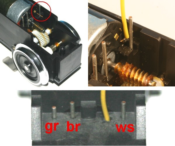
Old LGB gear boxes feature 3 leads, one pin (marked WS) is connected to track power and one of the two motor connectors.
For digital operation the motor connector must be separated from this pin.
The pictures show a simple conversion for digital operation:
- open the gear box and remove the electric motor (note the direction)
- shorten the motor contact which was touching the WS-pin by half bend this motor contact outwards and solder the fourth wire to it
- put the motor back into the gear box and make sure that the motor contact with the attached cable has no contact to the WS pin
- drill a fourth hole into the lid of the gear box to run the fourth wire through
- close the lid
Now you got all four wires that are required for digital operation.

Conversion of a half-shell LGB gear box to digital operation
In these old gear boxes both motor contacts are connected to track power.
The motor leads must be isolate from the track power leads on both sides.
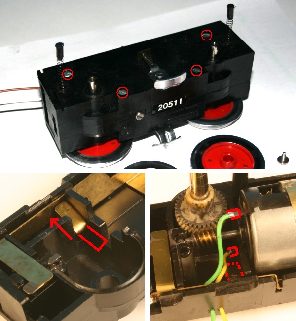
The pictures show a simple conversion for digital operation:
- remove the wheels on one side of the gear box and unscrew the four screws that hold the half-shells together. Watch out for the spring loaded carbon brushes!
- remove the electric motor (note the direction)
- bend the straps that contact the motor leads away from the motor leads (see pict.#2)
- solder wires (yellow and green) to the motor leads (see pict #3)
- put the motor back in the gear box and make sure that the motor leads do not touch the straps
- drill two holes in the upper side of the half-shells for the extra wires
- reassemble the gear box
Now all four leads necessary for digital operation are available.
The position for the wholes in the gear box may vary with the engine type, please check before reassembling the locomotive.
This gear box requires a different (slower) back-EMF setting, please check your decoder manual.

Preparing a PIKO gear box for digital operation (e.g. Taurus, BR218)
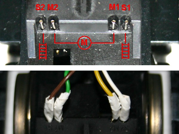
The Piko-Gear is ready for digital mode.
You have to notice 2 things:
- Against LGB-gears the pins are swapped! The Track connector (S1+S2) is outwards and the motor connector (M1+M2) is within.
- The pins are very closely together.
The connectors must be isolated with heat shrink tube or tape.

Back-fitting a Playmobil-gear to digital compatibility
In this type of gear are connected both sides of gear motor and track.
In digital mode you must separate motor and track.
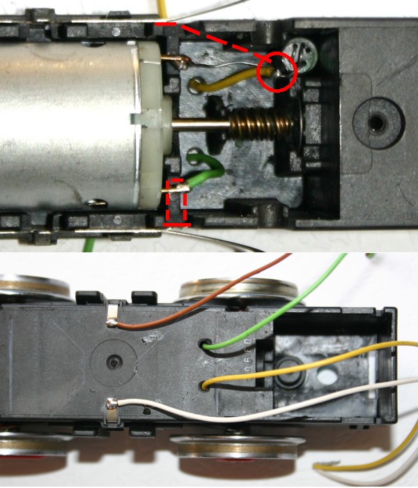
On the pictures you see a simple back-fitting suggestion:
- Remove the gear from the loco (push detent-clamp front + rear).
- Remove both screws on the lower side and remove cover with extend on the sliders.
- Remove the sheet plate on the motor. (Pict. 1)
- Pull the wire, who gets from the noise suppression choke to the contact plate, and shorten it. (Pict.1)
- Soldering a wire (yellow+green) on motor connector and the one wire of the noise suppression choke. (Pict. 1)
- Drill 2 holes in the cover and push the additional cables through it.
- Mount the gear.
- Soldering a cable (white+brown) on the bended plates at the cover plate (Pict. 2)
Now you have all connectors who your decoder need.
The feed-through of the additional cables could be different, addicted to the used loco (proof the space).


 Deutsch


